See Your Character
Build a complete NES cartridge from scratch — iNES header, PPU warmup, palette, and sprite data. A running figure appears on screen.
Black screen. Then a small figure appears — a runner, standing still, waiting.
The NES draws everything through a dedicated chip called the PPU (Picture Processing Unit). Your CPU can’t touch the screen directly. Instead, you set up data — palettes, tiles, sprite positions — and the PPU reads it every frame. This separation is THE defining feature of NES programming. Everything you’ll learn in Dash flows from this one fact: the CPU sets up; the PPU draws.
This unit builds a complete NES cartridge: the header that identifies the ROM, the startup code that prepares the hardware, the colour palette, the tile graphics, and one sprite positioned on screen. By the end, you’ll have a running figure on a black background — the first frame of Dash.
The Cartridge Header
Every NES ROM begins with a 16-byte header. The emulator reads it to know what kind of cartridge it’s dealing with:
.segment "HEADER"
    .byte "NES", $1A        ; Magic number — every NES ROM starts with this
    .byte 2                 ; 2 x 16KB PRG-ROM = 32KB
    .byte 1                 ; 1 x 8KB CHR-ROM = 8KB
    .byte $01               ; Vertical mirroring, Mapper 0
    .byte $00               ; Mapper 0 (NROM)
    .byte 0,0,0,0,0,0,0,0  ; Padding
.segment "HEADER" tells ca65 to place these bytes at the start of the ROM file. “NES” followed by $1A is the magic number — every NES ROM starts with these four bytes.
The next two bytes define the ROM size. 2 means two banks of 16KB PRG-ROM (the code — 32KB total). 1 means one bank of 8KB CHR-ROM (the graphics). This is Mapper 0, the simplest NES cartridge — no bank switching, no special hardware. Just code and graphics.
Starting Up
When the NES powers on, it jumps to the address stored at $FFFC — the reset vector. Our reset routine prepares the hardware:
reset:
    sei                     ; Disable interrupts
    cld                     ; Clear decimal mode (6502 habit, not used on NES)
    ldx #$40
    stx $4017               ; Disable APU frame IRQ
    ldx #$FF
    txs                     ; Set up stack pointer
    inx                     ; X = 0
    stx PPUCTRL             ; Disable NMI
    stx PPUMASK             ; Disable rendering
    stx $4010               ; Disable DMC IRQs

    ; Wait for PPU to stabilise (first vblank)
@vblank1:
    bit PPUSTATUS
    bpl @vblank1

    ; Clear all RAM while we wait for the second vblank
    lda #0
@clear_ram:
    sta $0000, x
    sta $0100, x
    sta $0200, x
    sta $0300, x
    sta $0400, x
    sta $0500, x
    sta $0600, x
    sta $0700, x
    inx
    bne @clear_ram

    ; Wait for PPU (second vblank)
@vblank2:
    bit PPUSTATUS
    bpl @vblank2
There’s a lot here, and we’ll revisit the details in later units. The essentials:
SEI disables interrupts while we set up. CLD clears decimal mode — a 6502 feature the NES doesn’t use, but good practice to disable. We set the stack pointer to $FF (the top of the stack page at $0100–$01FF) and disable the PPU and sound hardware.
Then we wait. The PPU needs two full video frames (vblanks) before it’s stable. BIT PPUSTATUS reads register $2002 — bit 7 goes high when the PPU enters vblank. BPL loops until that bit is set. Between the two waits, we clear all 2KB of RAM to zero — useful work while the PPU catches up.
After the second vblank, the PPU is ready to accept data.
Loading Colours
The NES uses palettes — small tables of colours that everything on screen references. Background tiles use one set of four palettes. Sprites use another set of four. Each palette holds four colours.
To write palette data, we use the PPU address protocol — a pattern you’ll see constantly in NES programming:
    ; Load palette data into PPU
    bit PPUSTATUS           ; Reset address latch
    lda #$3F
    sta PPUADDR
    lda #$00
    sta PPUADDR             ; PPU address = $3F00 (palette)

    ldx #0
@load_palette:
    lda palette_data, x
    sta PPUDATA
    inx
    cpx #32
    bne @load_palette
First, read PPUSTATUS ($2002) to reset the internal address latch. Then write the target address to PPUADDR ($2006) — high byte first, then low byte. Now write data bytes to PPUDATA ($2007). The PPU auto-increments the address after each write.
$3F00 is where palette data lives in PPU memory. We write 32 bytes: 16 for background palettes, 16 for sprite palettes. The loop reads from palette_data in our code and feeds each byte to the PPU through PPUDATA.
Our sprite palette 0 is: $0F (black — the transparent colour), $30 (white), $16 (red), $27 (orange). The running figure will appear in white — colour index 1 of this palette.
The Two-Write Address Pattern
This two-write protocol (PPUADDR twice, then PPUDATA) exists because the PPU has its own separate address bus. The CPU can’t just write to a PPU address directly — it must go through the registers at $2006 and $2007. This is the CPU/PPU boundary in action.
Placing the Sprite
The NES supports 64 hardware sprites — small moveable graphics layered over the background. Each sprite is defined by four bytes in OAM (Object Attribute Memory):
| Byte | Purpose |
|---|---|
| 0 | Y position (row on screen) |
| 1 | Tile number (which 8×8 graphic to draw) |
| 2 | Attributes (palette, flip, priority) |
| 3 | X position (column on screen) |
We keep a 256-byte OAM buffer in RAM at $0200 and write the player sprite to the first four bytes:
    ; Set up player sprite in OAM buffer
    lda #PLAYER_Y
    sta oam_buffer+0        ; Y position
    lda #PLAYER_TILE
    sta oam_buffer+1        ; Tile number
    lda #0
    sta oam_buffer+2        ; Attributes (palette 0, no flip)
    lda #PLAYER_X
    sta oam_buffer+3        ; X position

    ; Hide all other sprites (Y = $EF moves off visible screen)
    lda #$EF
    ldx #4
@hide_sprites:
    sta oam_buffer, x
    inx
    bne @hide_sprites
Y first, then tile number, then attributes, then X. The order matters — it’s how the PPU hardware expects the data. Tile 1 is our running figure (tile 0 is empty). Attributes $00 means palette 0 and no flipping.
The loop after hides all 63 other sprites by setting their Y positions to $EF (239), which pushes them below the visible area on NTSC.
After setting up sprites, two writes turn the screen on:
    lda #%10000000         ; Bit 7: enable NMI
    sta PPUCTRL
    lda #%00011110         ; Bits 1-4: show background and sprites
    sta PPUMASK
Bit 7 of PPUCTRL enables the NMI interrupt — the PPU will now call our NMI handler every frame. PPUMASK bits 1–4 enable background and sprite rendering. The screen comes alive.
Then the main loop: an infinite JMP back to itself. The CPU has nothing to do between frames. All the action happens in the NMI handler.
The NMI Handler
Every 1/60th of a second (on NTSC), the PPU finishes drawing the screen and enters vblank — a brief window where the CPU can safely update PPU data. The PPU fires an NMI (Non-Maskable Interrupt), which jumps to our handler:
nmi:
    pha                     ; Save A
    txa
    pha                     ; Save X
    tya
    pha                     ; Save Y

    ; Copy OAM buffer to PPU via DMA
    lda #0
    sta OAMADDR
    lda #>oam_buffer        ; High byte of buffer address ($02)
    sta OAMDMA              ; Triggers 256-byte DMA transfer

    pla                     ; Restore Y
    tay
    pla                     ; Restore X
    tax
    pla                     ; Restore A
    rti
The handler’s one job right now: copy the OAM buffer from RAM to the PPU. Writing the high byte of the buffer address ($02 for $0200) to OAMDMA ($4014) triggers a hardware DMA transfer — all 256 bytes copied in one shot. Every sprite updated in a single write.
PHA/PLA save and restore the CPU registers (A, X, Y) around the handler. The NMI interrupts whatever the main loop was doing — without saving and restoring, it would corrupt the main program’s state. RTI returns from the interrupt.
The Tile Data
NES graphics are tiles — 8×8 pixel images stored in CHR-ROM. Each tile uses 16 bytes: 8 bytes for bit plane 0, then 8 bytes for bit plane 1. The two planes combine to give each pixel a 2-bit colour index (0–3). For sprites, index 0 is transparent.
; Tile 1: Running figure
;
;   ..##....    Head
;   ..##....    Head
;   .####...    Arms + body
;   ..##....    Torso
;   ..##....    Hips
;   ..#.#...    Legs mid-stride
;   .#...#..    Legs apart
;   .#...#..    Feet
;
.byte %00110000             ; Plane 0 (bit 0 of each pixel)
.byte %00110000
.byte %01111000
.byte %00110000
.byte %00110000
.byte %00101000
.byte %01000100
.byte %01000100
.byte %00000000             ; Plane 1 (bit 1 — all zero = colour 1 only)
.byte %00000000
.byte %00000000
.byte %00000000
.byte %00000000
.byte %00000000
.byte %00000000
.byte %00000000
Read the bit patterns as pixels: 1 = drawn, 0 = empty. The figure has a head (two pixels wide), arms stretched out across the body, a torso, and legs mid-stride. Plane 1 is all zeros, so every set pixel uses colour index 01 — colour 1 from the sprite palette, which is white.
The Linker Config
The .segment directives in the code don’t mean anything without a linker configuration that maps them to actual memory. The nes.cfg file tells ld65 where everything goes:
MEMORY {
    ZP:     start = $00,    size = $100,   type = rw, file = "";
    OAM:    start = $0200,  size = $100,   type = rw, file = "";
    RAM:    start = $0300,  size = $500,   type = rw, file = "";
    HEADER: start = $0,     size = $10,    type = ro, file = %O, fill = yes;
    PRG:    start = $8000,  size = $8000,  type = ro, file = %O, fill = yes;
    CHR:    start = $0,     size = $2000,  type = ro, file = %O, fill = yes;
}ZP, OAM, and RAM are in the NES’s 2KB work RAM. file = "" means they don’t appear in the output file — they’re runtime memory only. HEADER, PRG, and CHR are written to the .nes file (file = %O). PRG starts at $8000 — the NES maps cartridge ROM there. CHR is the 8KB graphics bank. The fill = yes pads each region to its full size.
The SEGMENTS block (in the full file) maps each .segment directive to a memory region. This is how HEADER bytes end up at the start of the file, CODE ends up in PRG-ROM, and CHARS ends up in CHR-ROM.
Building
Two commands:
ca65 dash.asm -o dash.o
ld65 -C nes.cfg dash.o -o dash.nes
ca65 assembles the source into an object file. ld65 links it using the config to produce the final .nes ROM. Open it in an emulator — Mesen, FCEUX, or any NES emulator.
The Complete Code
; =============================================================================
; DASH - Unit 1: See Your Character
; =============================================================================
; A running figure on a black screen. The first step toward a platformer.
; =============================================================================

; -----------------------------------------------------------------------------
; NES Hardware Addresses
; -----------------------------------------------------------------------------
PPUCTRL   = $2000           ; PPU control register
PPUMASK   = $2001           ; PPU mask register
PPUSTATUS = $2002           ; PPU status register
OAMADDR   = $2003           ; OAM address
PPUADDR   = $2006           ; PPU address
PPUDATA   = $2007           ; PPU data
OAMDMA    = $4014           ; OAM DMA register

; -----------------------------------------------------------------------------
; Game Constants
; -----------------------------------------------------------------------------
PLAYER_X    = 124           ; Starting X position
PLAYER_Y    = 120           ; Starting Y position
PLAYER_TILE = 1             ; Tile number for the player sprite

; -----------------------------------------------------------------------------
; Memory
; -----------------------------------------------------------------------------
.segment "ZEROPAGE"
player_x:   .res 1          ; Player X position
player_y:   .res 1          ; Player Y position

.segment "OAM"
oam_buffer: .res 256        ; Sprite data (DMA'd to PPU each frame)

.segment "BSS"
; General RAM variables go here

; =============================================================================
; iNES Header
; =============================================================================
.segment "HEADER"
    .byte "NES", $1A        ; Magic number — every NES ROM starts with this
    .byte 2                 ; 2 x 16KB PRG-ROM = 32KB
    .byte 1                 ; 1 x 8KB CHR-ROM = 8KB
    .byte $01               ; Vertical mirroring, Mapper 0
    .byte $00               ; Mapper 0 (NROM)
    .byte 0,0,0,0,0,0,0,0  ; Padding

; =============================================================================
; Code
; =============================================================================
.segment "CODE"

; --- Reset: runs when the NES powers on ---
reset:
    sei                     ; Disable interrupts
    cld                     ; Clear decimal mode (6502 habit, not used on NES)
    ldx #$40
    stx $4017               ; Disable APU frame IRQ
    ldx #$FF
    txs                     ; Set up stack pointer
    inx                     ; X = 0
    stx PPUCTRL             ; Disable NMI
    stx PPUMASK             ; Disable rendering
    stx $4010               ; Disable DMC IRQs

    ; Wait for PPU to stabilise (first vblank)
@vblank1:
    bit PPUSTATUS
    bpl @vblank1

    ; Clear all RAM while we wait for the second vblank
    lda #0
@clear_ram:
    sta $0000, x
    sta $0100, x
    sta $0200, x
    sta $0300, x
    sta $0400, x
    sta $0500, x
    sta $0600, x
    sta $0700, x
    inx
    bne @clear_ram

    ; Wait for PPU (second vblank)
@vblank2:
    bit PPUSTATUS
    bpl @vblank2

    ; === PPU is ready ===

    ; Load palette data into PPU
    bit PPUSTATUS           ; Reset address latch
    lda #$3F
    sta PPUADDR
    lda #$00
    sta PPUADDR             ; PPU address = $3F00 (palette)

    ldx #0
@load_palette:
    lda palette_data, x
    sta PPUDATA
    inx
    cpx #32
    bne @load_palette

    ; Set up player sprite in OAM buffer
    lda #PLAYER_Y
    sta oam_buffer+0        ; Y position
    lda #PLAYER_TILE
    sta oam_buffer+1        ; Tile number
    lda #0
    sta oam_buffer+2        ; Attributes (palette 0, no flip)
    lda #PLAYER_X
    sta oam_buffer+3        ; X position

    ; Store position in variables
    lda #PLAYER_X
    sta player_x
    lda #PLAYER_Y
    sta player_y

    ; Hide all other sprites (Y = $EF moves off visible screen)
    lda #$EF
    ldx #4
@hide_sprites:
    sta oam_buffer, x
    inx
    bne @hide_sprites

    ; Enable rendering
    lda #%10000000          ; Enable NMI
    sta PPUCTRL
    lda #%00011110          ; Show background and sprites
    sta PPUMASK

; --- Main loop ---
main_loop:
    jmp main_loop           ; Nothing to do yet — wait for NMI

; --- NMI: runs every frame during vblank ---
nmi:
    pha                     ; Save A
    txa
    pha                     ; Save X
    tya
    pha                     ; Save Y

    ; Copy OAM buffer to PPU via DMA
    lda #0
    sta OAMADDR
    lda #>oam_buffer        ; High byte of buffer address ($02)
    sta OAMDMA              ; Triggers 256-byte DMA transfer

    pla                     ; Restore Y
    tay
    pla                     ; Restore X
    tax
    pla                     ; Restore A
    rti

; --- IRQ: not used ---
irq:
    rti

; =============================================================================
; Data
; =============================================================================

palette_data:
    ; Background palettes
    .byte $0F, $00, $10, $20   ; Palette 0: black, dark grey, grey, light grey
    .byte $0F, $00, $10, $20   ; Palette 1
    .byte $0F, $00, $10, $20   ; Palette 2
    .byte $0F, $00, $10, $20   ; Palette 3
    ; Sprite palettes
    .byte $0F, $30, $16, $27   ; Palette 0: transparent, white, red, orange
    .byte $0F, $30, $16, $27   ; Palette 1
    .byte $0F, $30, $16, $27   ; Palette 2
    .byte $0F, $30, $16, $27   ; Palette 3

; =============================================================================
; Vectors
; =============================================================================
.segment "VECTORS"
    .word nmi               ; NMI vector (called every vblank)
    .word reset             ; Reset vector (called on power-on)
    .word irq               ; IRQ vector (not used)

; =============================================================================
; CHR-ROM (Graphics)
; =============================================================================
.segment "CHARS"

; Tile 0: Empty (all transparent)
.byte $00,$00,$00,$00,$00,$00,$00,$00  ; Plane 0
.byte $00,$00,$00,$00,$00,$00,$00,$00  ; Plane 1

; Tile 1: Running figure
;
;   ..##....    Head
;   ..##....    Head
;   .####...    Arms + body
;   ..##....    Torso
;   ..##....    Hips
;   ..#.#...    Legs mid-stride
;   .#...#..    Legs apart
;   .#...#..    Feet
;
.byte %00110000             ; Plane 0 (bit 0 of each pixel)
.byte %00110000
.byte %01111000
.byte %00110000
.byte %00110000
.byte %00101000
.byte %01000100
.byte %01000100
.byte %00000000             ; Plane 1 (bit 1 — all zero = colour 1 only)
.byte %00000000
.byte %00000000
.byte %00000000
.byte %00000000
.byte %00000000
.byte %00000000
.byte %00000000

; Fill rest of CHR-ROM with empty tiles
.res 8192 - 32, $00
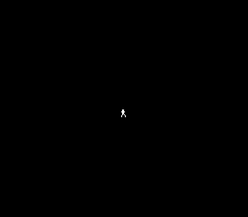
A small white figure on a black screen. Head, arms, legs — recognisably a runner, standing at the centre of the screen. The PPU draws it every frame at 60fps, reading the tile from CHR-ROM and the position from OAM.
Try This: Move the Sprite
Change the starting position constants near the top:
PLAYER_X    = 124
PLAYER_Y    = 120
Set X to 40 and Y to 200. Rebuild. The figure moves to the bottom-left.
The visible screen area is roughly 0–255 for X and 8–231 for Y. Values outside this range push the sprite partially or fully off-screen.
Try This: Change the Colours
Find the sprite palette in palette_data:
.byte $0F, $30, $16, $27 ; Palette 0: transparent, white, red, orangeChange $30 (white) to $15 (pink), $1A (green), or $12 (blue). Rebuild. The figure changes colour.
The NES has a fixed set of 54 unique colours. The four values in each palette entry select from this fixed set — you don’t define RGB values, you pick from what the hardware provides.
Try This: Redesign the Sprite
The tile data is just bit patterns. Change the figure:
.byte %00111100             ; Wider head
.byte %00111100
.byte %01111110             ; Broad shoulders
.byte %00111100
.byte %00011000             ; Narrow waist
.byte %00111100
.byte %01100110             ; Wide stance
.byte %01000010
Each row is 8 pixels. Sketch on graph paper first — it helps.
If It Doesn’t Work
- Black screen? Check
PPUMASKis set to$1E(rendering enabled). CheckPPUCTRLhas bit 7 set (NMI enabled). Without NMI, the OAM DMA never runs. - No sprite?
PPUMASKbit 4 must be 1 to show sprites. Check the NMI handler writes to$4014. - Wrong tile? The tile number in OAM (byte 1) must match the tile’s position in CHR-ROM. Tile 0 starts at offset 0, tile 1 at offset 16.
- Wrong colour? Check sprite palette data at
$3F10–$3F13. Colour 1 is the second byte. Make sure the tile data uses plane 0 only (plane 1 all zeros). - Sprite at wrong position? OAM format is Y, tile, attributes, X — not X, Y. Getting these swapped puts the sprite somewhere unexpected.
- Build error? Check
nes.cfgis in the same directory asdash.asm. The-C nes.cfgflag tellsld65where to find it.
What You’ve Learnt
- CPU/PPU separation — the CPU can’t draw pixels directly. It writes data to PPU registers, and the PPU reads that data to draw the screen. This boundary defines NES programming.
- iNES header — 16 bytes at the start of every ROM: magic number, PRG-ROM size, CHR-ROM size, mapper number. The emulator needs this to emulate the cartridge correctly.
- PPU address protocol — read
PPUSTATUSto reset the latch, write high then low byte toPPUADDR, then write data toPPUDATA. This is how you talk to the PPU. - Palettes — 32 bytes at PPU address
$3F00. Four background palettes + four sprite palettes, each holding four colours from the NES’s fixed colour set. - OAM format — each sprite is 4 bytes: Y position, tile number, attributes, X position. 64 sprites total, 256 bytes of OAM.
- OAM DMA — writing the buffer’s high byte to
$4014transfers all 256 bytes at once. Do this every frame in the NMI handler. - CHR-ROM tiles — 16 bytes per 8×8 tile, stored as two bit planes. The planes combine to give each pixel a 2-bit colour index (0–3).
- NMI interrupt — the PPU fires NMI every frame during vblank. Your handler runs, updates sprites, and returns. The game breathes at 60Hz.
What’s Next
The figure stands motionless. In Unit 2, you’ll read the NES controller and make it move left and right — the first interaction in Dash.