Draw Terrain
Filled rectangles build a landscape in the bitplane. A subroutine draws byte-aligned rectangles. Three calls create ground, a cliff, and a platform.
Unit 2 filled everything below a line with terrain — one flat horizon. Real landscapes have shape: high ground, low ground, ledges, gaps. This unit draws terrain directly into the bitplane using a reusable subroutine.
The CPU writes rectangles of set bits into the bitplane. Where bits are 1, COLOR01 (terrain brown) appears. Where they’re 0, the sky gradient shows through. Three rectangles build a landscape with a cliff face and a floating platform.
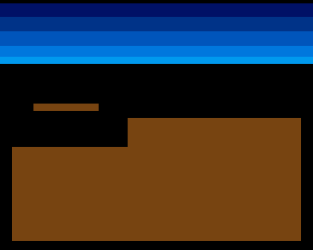
Low ground on the left. High ground on the right, forming a cliff face where the two levels meet. A floating platform hangs above the step. This is the start of a real terrain puzzle — later, creatures will need to navigate these features.
Subroutines: BSR and RTS
Until now, all code ran in a straight line from top to bottom. But drawing three rectangles with the same logic means repeating the same code three times — or using a subroutine.
BSR (Branch to Subroutine) pushes the return address onto the stack and jumps to a label. RTS (Return from Subroutine) pops that address and jumps back. The calling code resumes exactly where it left off:
            bsr     draw_rect       ; Jump to draw_rect, push return address
            ; ...execution continues here after RTS
This is the 68000’s equivalent of a function call. Parameters go in registers before the call. The subroutine does its work and returns.
The draw_rect Subroutine
;──────────────────────────────────────────────────────────────
; draw_rect — Fill a byte-aligned rectangle in the bitplane
;
; Input:  D0.W = x position (must be multiple of 8)
;         D1.W = y position
;         D2.W = width in pixels (must be multiple of 8)
;         D3.W = height in pixels
; Destroys: D0-D5, A0-A1
;──────────────────────────────────────────────────────────────
draw_rect:
            ; Calculate starting address: bitplane + y*40 + x/8
            lea     bitplane,a0
            mulu    #BYTES_PER_ROW,d1   ; D1 = y * 40 (32-bit result)
            add.l   d1,a0               ; A0 += y offset
            lsr.w   #3,d0               ; D0 = x / 8
            add.w   d0,a0               ; A0 += x offset

            ; Convert width from pixels to bytes
            lsr.w   #3,d2               ; D2 = width / 8

            ; Outer loop: rows
            subq.w  #1,d3               ; Height - 1 for DBRA
.row:
            move.w  d2,d5
            subq.w  #1,d5               ; Width_bytes - 1 for DBRA
            move.l  a0,a1               ; A1 = row write pointer
.col:
            move.b  #$ff,(a1)+          ; Fill 8 pixels (one byte)
            dbra    d5,.col

            add.w   #BYTES_PER_ROW,a0   ; Advance to next row
            dbra    d3,.row
            rts
The subroutine takes four parameters in D0-D3: x position, y position, width, and height. All coordinates are in pixels, but x and width must be multiples of 8 (byte-aligned) to keep the drawing simple.
Address calculation — the starting byte in the bitplane is y × 40 + x ÷ 8. MULU (Multiply Unsigned) computes y × BYTES_PER_ROW as a 32-bit result. LSR.W #3 shifts right by 3 bits, which divides by 8 — converting pixel positions to byte offsets.
Nested loops — the outer loop counts rows, the inner loop fills bytes across one row. Each byte written as $FF sets 8 pixels to 1. After each row, ADD.W #BYTES_PER_ROW,A0 advances the row pointer by 40 bytes to the next line.
DBRA in both loops — the inner loop uses D5 as a temporary copy of the width (in bytes), so the width value survives for the next row. The outer loop counts down in D3 (height). Both registers are pre-decremented by 1 because DBRA loops count+1 times.
Building the Landscape
Three calls to draw_rect build the terrain:
            ; --- Draw terrain into bitplane ---
            ; Bitplane starts as zeros (sky everywhere).
            ; Each draw_rect call fills a rectangle with 1s (terrain).

            ; Low ground (left side)
            move.w  #GROUND_L_X,d0
            move.w  #GROUND_L_Y,d1
            move.w  #GROUND_L_W,d2
            move.w  #GROUND_L_H,d3
            bsr     draw_rect

            ; High ground (right side — cliff face)
            move.w  #GROUND_R_X,d0
            move.w  #GROUND_R_Y,d1
            move.w  #GROUND_R_W,d2
            move.w  #GROUND_R_H,d3
            bsr     draw_rect

            ; Floating platform
            move.w  #PLATFORM_X,d0
            move.w  #PLATFORM_Y,d1
            move.w  #PLATFORM_W,d2
            move.w  #PLATFORM_H,d3
            bsr     draw_rect
Each call loads four values into D0-D3 and branches to the subroutine. The rectangles overlap where they need to — the low ground and high ground share the bottom of the screen.
The terrain parameters are defined as constants at the top of the file, making them easy to tweak:
; Low ground (left side)
GROUND_L_X          equ 0
GROUND_L_Y          equ 152
GROUND_L_W          equ 128
GROUND_L_H          equ 104

; High ground (right side — forms a cliff face)
GROUND_R_X          equ 128
GROUND_R_Y          equ 120
GROUND_R_W          equ 192
GROUND_R_H          equ 136

; Floating platform (above the step)
PLATFORM_X          equ 24
PLATFORM_Y          equ 104
PLATFORM_W          equ 72
PLATFORM_H          equ 8
Why Byte-Aligned?
The x position and width must be multiples of 8. This means every rectangle starts and ends on a byte boundary in the bitplane. Without this constraint, the first and last bytes of each row would need bit masking — setting some bits while preserving others. That’s more complex code for no visual benefit at this stage.
The Blitter can handle arbitrary pixel alignment efficiently. For now, byte-aligned rectangles keep the CPU drawing code simple and fast.
Experiment: Reshape the Terrain
Change the terrain constants to create different landscapes:
; Wide flat ground
GROUND_L_X          equ 0
GROUND_L_Y          equ 180
GROUND_L_W          equ 320
GROUND_L_H          equ 76
Or add a gap by making the left ground narrower:
GROUND_L_W equ 96 ; Narrower — gap before cliffTry moving the platform higher or making it wider. Every change is just a number — the subroutine handles the rest.
The Complete Code
;──────────────────────────────────────────────────────────────
; EXODUS - A terrain puzzle for the Commodore Amiga
; Unit 3: Draw Terrain
;
; Filled rectangles build a landscape in the bitplane.
; A subroutine (BSR/RTS) draws byte-aligned rectangles.
; Three calls create ground, a cliff, and a platform.
;──────────────────────────────────────────────────────────────

;══════════════════════════════════════════════════════════════
; TWEAKABLE VALUES
;══════════════════════════════════════════════════════════════

; Colours ($0RGB)
COLOUR_SKY_DEEP     equ $0016
COLOUR_SKY_UPPER    equ $0038
COLOUR_SKY_MID      equ $005B
COLOUR_SKY_LOWER    equ $007D
COLOUR_SKY_HORIZON  equ $009E

COLOUR_TERRAIN      equ $0741       ; Earth brown

; Terrain rectangles (x and width must be multiples of 8)
; Low ground (left side)
GROUND_L_X          equ 0
GROUND_L_Y          equ 152
GROUND_L_W          equ 128
GROUND_L_H          equ 104         ; Extends to bottom (152+104=256)

; High ground (right side — forms a cliff face)
GROUND_R_X          equ 128
GROUND_R_Y          equ 120
GROUND_R_W          equ 192
GROUND_R_H          equ 136         ; Extends to bottom (120+136=256)

; Floating platform (above the step)
PLATFORM_X          equ 24
PLATFORM_Y          equ 104
PLATFORM_W          equ 72
PLATFORM_H          equ 8

;══════════════════════════════════════════════════════════════
; DISPLAY CONSTANTS
;══════════════════════════════════════════════════════════════

SCREEN_WIDTH    equ 320
SCREEN_HEIGHT   equ 256
BYTES_PER_ROW   equ SCREEN_WIDTH/8      ; 40
BITPLANE_SIZE   equ BYTES_PER_ROW*SCREEN_HEIGHT  ; 10240

;══════════════════════════════════════════════════════════════
; HARDWARE REGISTERS
;══════════════════════════════════════════════════════════════

CUSTOM      equ $dff000
DMACON      equ $096
INTENA      equ $09a
INTREQ      equ $09c
COP1LC      equ $080
COPJMP1     equ $088
BPLCON0     equ $100
BPLCON1     equ $102
BPLCON2     equ $104
BPL1MOD     equ $108
DIWSTRT     equ $08e
DIWSTOP     equ $090
DDFSTRT     equ $092
DDFSTOP     equ $094
BPL1PTH     equ $0e0
BPL1PTL     equ $0e2
COLOR00     equ $180
COLOR01     equ $182
VPOSR       equ $004

;══════════════════════════════════════════════════════════════
; CODE (Chip RAM)
;══════════════════════════════════════════════════════════════

            section code,code_c

start:
            lea     CUSTOM,a5

            ; --- Take over the machine ---
            move.w  #$7fff,INTENA(a5)
            move.w  #$7fff,INTREQ(a5)
            move.w  #$7fff,DMACON(a5)

            ; --- Draw terrain into bitplane ---
            ; Bitplane starts as zeros (sky everywhere).
            ; Each draw_rect call fills a rectangle with 1s (terrain).

            ; Low ground (left side)
            move.w  #GROUND_L_X,d0
            move.w  #GROUND_L_Y,d1
            move.w  #GROUND_L_W,d2
            move.w  #GROUND_L_H,d3
            bsr     draw_rect

            ; High ground (right side — cliff face)
            move.w  #GROUND_R_X,d0
            move.w  #GROUND_R_Y,d1
            move.w  #GROUND_R_W,d2
            move.w  #GROUND_R_H,d3
            bsr     draw_rect

            ; Floating platform
            move.w  #PLATFORM_X,d0
            move.w  #PLATFORM_Y,d1
            move.w  #PLATFORM_W,d2
            move.w  #PLATFORM_H,d3
            bsr     draw_rect

            ; --- Patch bitplane pointer into Copper list ---
            lea     bitplane,a0
            move.l  a0,d0
            swap    d0
            lea     bpl1pth_val,a1
            move.w  d0,(a1)
            swap    d0
            lea     bpl1ptl_val,a1
            move.w  d0,(a1)

            ; --- Install Copper list ---
            lea     copperlist,a0
            move.l  a0,COP1LC(a5)
            move.w  d0,COPJMP1(a5)

            ; --- Enable DMA ---
            move.w  #$8380,DMACON(a5)   ; SET + DMAEN + COPEN + BPLEN

            ; === Main Loop ===
mainloop:
            move.l  #$1ff00,d1
.vbwait:
            move.l  VPOSR(a5),d0
            and.l   d1,d0
            bne.s   .vbwait

            btst    #6,$bfe001
            bne.s   mainloop

.halt:
            bra.s   .halt

;──────────────────────────────────────────────────────────────
; draw_rect — Fill a byte-aligned rectangle in the bitplane
;
; Input:  D0.W = x position (must be multiple of 8)
;         D1.W = y position
;         D2.W = width in pixels (must be multiple of 8)
;         D3.W = height in pixels
; Destroys: D0-D5, A0-A1
;──────────────────────────────────────────────────────────────
draw_rect:
            ; Calculate starting address: bitplane + y*40 + x/8
            lea     bitplane,a0
            mulu    #BYTES_PER_ROW,d1   ; D1 = y * 40 (32-bit result)
            add.l   d1,a0               ; A0 += y offset
            lsr.w   #3,d0               ; D0 = x / 8
            add.w   d0,a0               ; A0 += x offset

            ; Convert width from pixels to bytes
            lsr.w   #3,d2               ; D2 = width / 8

            ; Outer loop: rows
            subq.w  #1,d3               ; Height - 1 for DBRA
.row:
            move.w  d2,d5
            subq.w  #1,d5               ; Width_bytes - 1 for DBRA
            move.l  a0,a1               ; A1 = row write pointer
.col:
            move.b  #$ff,(a1)+          ; Fill 8 pixels (one byte)
            dbra    d5,.col

            add.w   #BYTES_PER_ROW,a0   ; Advance to next row
            dbra    d3,.row
            rts

;══════════════════════════════════════════════════════════════
; COPPER LIST
;══════════════════════════════════════════════════════════════

copperlist:
            ; --- Display window (standard PAL low-res) ---
            dc.w    DIWSTRT,$2c81
            dc.w    DIWSTOP,$2cc1
            dc.w    DDFSTRT,$0038
            dc.w    DDFSTOP,$00d0

            ; --- Bitplane configuration ---
            dc.w    BPLCON0,$1200       ; 1 bitplane + colour burst
            dc.w    BPLCON1,$0000
            dc.w    BPLCON2,$0000
            dc.w    BPL1MOD,$0000

            ; --- Bitplane pointer (patched by CPU) ---
            dc.w    BPL1PTH
bpl1pth_val:
            dc.w    $0000
            dc.w    BPL1PTL
bpl1ptl_val:
            dc.w    $0000

            ; --- Colours ---
            dc.w    COLOR00,COLOUR_SKY_DEEP
            dc.w    COLOR01,COLOUR_TERRAIN

            ; --- SKY GRADIENT ---
            dc.w    $3401,$fffe
            dc.w    COLOR00,COLOUR_SKY_UPPER

            dc.w    $4401,$fffe
            dc.w    COLOR00,COLOUR_SKY_MID

            dc.w    $5401,$fffe
            dc.w    COLOR00,COLOUR_SKY_LOWER

            dc.w    $6001,$fffe
            dc.w    COLOR00,COLOUR_SKY_HORIZON

            ; Black background below sky
            dc.w    $6801,$fffe
            dc.w    COLOR00,$0000

            ; --- END ---
            dc.w    $ffff,$fffe

;══════════════════════════════════════════════════════════════
; BITPLANE DATA (10,240 bytes — all zeros = sky)
;══════════════════════════════════════════════════════════════

            even
bitplane:
            dcb.b   BITPLANE_SIZE,0
If It Doesn’t Work
- No terrain visible? Check that the three
BSR draw_rectcalls happen before the Copper list is installed. The bitplane must be filled before the display starts reading it. - Rectangle in wrong position? Remember that x and width are in pixels but must be multiples of 8. If
GROUND_L_Xis 10, theLSR #3rounds it down to byte 1 (pixel 8), not pixel 10. - Only one rectangle appears? The subroutine destroys D0-D5. Each call must reload all four parameters fresh — you can’t reuse values from a previous call.
- Crash or garbage? Check that
draw_rectends withRTS. Without it, execution falls through into whatever comes next — the Copper list data, which is not valid code.
What You’ve Learnt
- BSR/RTS — subroutine call and return. BSR pushes the return address onto the stack; RTS pops it and jumps back. Parameters pass through registers.
- MULU — unsigned 16×16→32 multiply. Used here to compute row offsets (
y × 40). - Nested DBRA loops — an outer loop for rows and an inner loop for columns. The inner counter is reset from a preserved copy each row.
- Byte-aligned drawing — restricting x and width to multiples of 8 avoids bit masking. Each byte written sets exactly 8 pixels.
- Terrain as data — the landscape is defined by a few constants. The same subroutine draws any rectangle, making the terrain easy to reshape.
What’s Next
The terrain is static — drawn once at startup. In Unit 4, a hardware sprite appears on screen. Sprites float independently of the bitplane, drawn by the custom chips without touching the bitmap. This is how the player’s cursor or a creature will appear over the terrain.