
Press A. TURN 0 becomes TURN 1. Do it again for TURN 2. Walk away for a cup of tea and the world waits for you. That is a useful game loop for an adventure, a board game or any other untimed decision.
X leaves the count alone. Q returns to BASIC. The counter stands in for the world update: spend a move, change a room or let the opponents respond only when the command earns it.
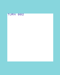
Start the complete caller
This entry uses a PAL VIC-20 with BASIC V2 and no RAM expansion. Keep its normal firmware running: the keyboard reader depends on the firmware interrupt service and default keyboard channel. These are delivered characters, rather than a test for one fresh physical press.
Keep demo.asm, caller.inc, routines.inc and presentation.inc together. With Asm198x available:
make -C commodore-vic-20/patterns/assembly/framework/command-loop ASM198X=/path/to/asm198xThe output is build/demo.prg, loaded at $1001. RUN executes its SYS 4112 stub. The verified emulator route imports the PRG through its program slot and lets the ROM execute RUN/SYS. That proves the imported program’s execution, not a tape or disk transfer.
Machine-specific BASIC launch stub and assembly includes
*=$1001
    !word basic_end
    !word 10
    !byte $9e
    !text "4112"
    !byte 0
basic_end:
    !word 0
    !fill $1010-*,0
    !source "caller.inc"
    !source "routines.inc"
    !source "presentation.inc"
Keep firmware services alive while waiting for a character
start:
    cld
    lda #0
    sta turn_count
    lda #1
    sta turn_step
redraw:
    jsr draw_count
read_command:
    jsr $ffe4
    cmp #0
    beq read_command
    cmp #81
    beq quit
    jsr apply_command
    jmp redraw
quit:
    rts
GETIN at $FFE4 returns a queued character in A, or zero when none is available. The zero case goes back to reading without updating the world. Q returns through the original SYS call stack. Do not reset the stack or replace the firmware IRQ as if this were a standalone cartridge.
Reuse the command update
Include routines.inc in your own program. Clear decimal mode with CLD, initialise the two state bytes once, place the command’s PETSCII value in A and JSR apply_command.
Byte state and a rule with no I/O
; In: A=PETSCII command, turn_count/turn_step bytes.
; Out: turn_accepted=1 for A ($41), otherwise 0.
; Preserves X/Y. Clobbers A and processor flags; decimal mode must be clear.
apply_command:
    pha
    lda #0
    sta turn_accepted
    pla
    cmp #65
    bne command_done
    lda turn_count
    clc
    adc turn_step
    sta turn_count
    lda #1
    sta turn_accepted
command_done:
    rts
turn_count: !byte 0
turn_step: !byte 1
turn_accepted: !byte 0| Resource | Contract |
|---|---|
| A on entry | PETSCII command; $41 is A |
turn_count |
Persistent byte, updated modulo 256 for A |
turn_step |
Byte amount to add; preserved |
turn_accepted |
Replaced: 1 for A, 0 otherwise |
| Registers | X/Y preserved; A and flags changed; D must be clear |
The routine uses three state bytes and the normal hardware stack, with no zero-page scratch. CLC supplies the starting carry for ADC; byte arithmetic discards overflow past 255. The CLD in the caller matters because decimal-mode arithmetic would change that meaning.
The labelled bytes move with your code. Keep their allocation and contents intact between calls. The complete PRG occupies BASIC program RAM; reserve that loaded range if you combine it with BASIC, and relocate it deliberately when combining assembly modules.
Keep presentation separate
presentation.inc clears the screen and prints three decimal digits. It uses firmware CHROUT at $FFD2, two scratch bytes, A/X/Y and flags. It assumes the default screen output channel. Its repeated-subtraction conversion is easy to follow and bounded by the byte-sized count; a larger score needs a different conversion.
Caller-owned screen output, separate from the rule
; Caller-owned presentation. Clears the screen and prints one counter.
; Clobbers A/X/Y, flags and print_value/print_digit; default screen channel only.
draw_count:
    lda #147
    jsr $ffd2
    lda #84
    jsr $ffd2
    lda #85
    jsr $ffd2
    lda #82
    jsr $ffd2
    lda #78
    jsr $ffd2
    lda #32
    jsr $ffd2
    lda turn_count
    sta print_value
    lda #48
    sta print_digit
hundreds:
    lda print_value
    cmp #100
    bcc emit_hundreds
    sec
    sbc #100
    sta print_value
    inc print_digit
    bne hundreds
emit_hundreds:
    lda print_digit
    jsr $ffd2
    lda #48
    sta print_digit
tens:
    lda print_value
    cmp #10
    bcc emit_tens
    sec
    sbc #10
    sta print_value
    inc print_digit
    bne tens
emit_tens:
    lda print_digit
    jsr $ffd2
    lda print_value
    clc
    adc #48
    jsr $ffd2
    lda #13
    jmp $ffd2
print_value: !byte 0
print_digit: !byte 0
This is why the same rule can serve two different interfaces. You can retain apply_command while replacing the screen clear with a status-field update. Firmware keyboard scanning, screen workspace and stack use still belong to the firmware. A takeover loop that disables IRQs or hides ROM cannot keep this reader unchanged.
Make it your own
Replace caller.inc with this variant when assembling. The immediate step becomes 3: two As show 000 → 003 → 006.
A different step, with the same state and code size
start:
    cld
    lda #0
    sta turn_count
    lda #3
    sta turn_step
redraw:
    jsr draw_count
read_command:
    jsr $ffe4
    cmp #0
    beq read_command
    cmp #81
    beq quit
    jsr apply_command
    jmp redraw
quit:
    rts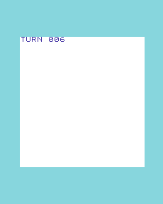
No extra code bytes, state or artwork are needed. One accepted command is still one update. Replace only the caller include, rather than including two copies of its labels.
Common mistake: resetting persistent state
The following caller is deliberately broken. It saves the incoming command, clears the count, restores the command and then calls the rule.
Broken: erase the count before interpreting every command
start:
    cld
    lda #0
    sta turn_count
    lda #1
    sta turn_step
redraw:
    jsr draw_count
read_command:
    jsr $ffe4
    cmp #0
    beq read_command
    cmp #81
    beq quit
    pha
    lda #0
    sta turn_count
    pla
    jsr apply_command
    jmp redraw
quit:
    rts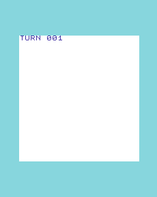
A, X, A produces 001 → 000 → 001. The smallest repair is to remove that reset from the loop and restore the original caller; its startup initialisation remains. The repaired path is checked separately. Forgetting CLD or replacing firmware services would be different faults; these captures demonstrate the reset mistake only.
When the world cannot wait
This caller consumes CPU while polling the firmware buffer. Neither approach supplies a turn deadline. The machine’s clocks continue, but the rule state waits. For a countdown, animated cursor or sound service that needs regular calls, retain the rule and replace the waiting policy. Decide what happens if a valid command and an expired deadline arrive together.
The loop comparison separates progression, time, input and presentation. These choices can be combined; they are not a compulsory ladder from BASIC to assembly.
The VIC-20 basic caller implements the same small rule with its own language contract. Assembly owns its bytes and calls the firmware directly.
Take the source and evidence
Code status: native-emulator executed, using Emu198x 0.44.1 and the named configuration above. The assembly build uses Asm198x 0.0.71 and the PRG/ROM launch route described above. No host write supplies the counter state.
The source folder keeps the caller, routine, customisation, deliberately broken caller and native record together. The source, ROM hashes and released tool identities are bound in that record.
Six separately started variants cover normal use, step three, the reset fault and repair, byte wraparound and a nonzero start with step 255. Each waits 120 native fields before and after an action, submits X and two As, checks the visible counter and returns to BASIC with Q. The retained checker decodes screen RAM and compares it with independent arithmetic; altered counts, blank screens, absent observations and changed image hashes must fail. The figures are actual framebuffer captures.
These checks establish this small workload. They do not qualify original hardware, every firmware/display variant, a full parser, or the whole emulator.
Original references
Commodore, VIC-20 Programmer’s Reference Guide, KERNAL routine reference (GETIN, CHROUT); The Complete Commodore Inner Space Anthology, p. 27 (BASIC 4.0/2.0 routines) and p. 28 (VIC/C64 routines). PET execution is qualified with its own ROMs, not inferred from a shared address.