
ANTIC and GTIA divide the Atari 8-bit computers’ picture into two connected jobs. ANTIC follows a display list and fetches display data from memory. GTIA interprets the resulting pixel information, combines it with player/missile graphics, applies priority and selects colours. Understanding that boundary explains how Atari could add new colour modes without giving ANTIC a completely different display-list language.
ANTIC does the fetching
A display list tells ANTIC which modes to use down the screen. Some instructions leave blank lines; others display character or bitmap data. A load-memory-scan instruction supplies a new data address. The CPU can assemble a screen from different modes and memory areas instead of committing the whole frame to one uniform layout. (De Re Atari, chapters 2–3.)
ANTIC performs direct memory access for those fetches. Those accesses take time on the shared memory system, so the 6502 cannot use every nominal processor cycle for its own work. Wider or more demanding displays change the budget available to code.
A display-list interrupt gives the CPU a chance to alter registers at a chosen point in the frame. The list establishes when to interrupt; the handler does the register changes. It is a timed interaction between hardware and software, not an unlimited second processor running arbitrary game code.
GTIA changes the interpretation
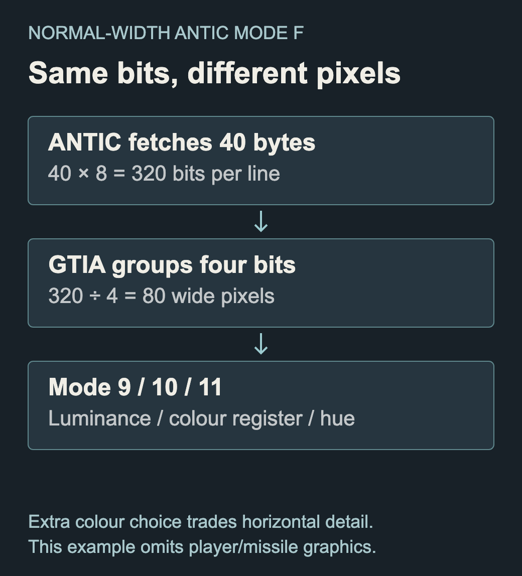
Earlier machines used CTIA. GTIA adds three display interpretations, conventionally called modes 9, 10 and 11. Used with ANTIC’s high-resolution bitmap mode, groups of four fetched bits form one of eighty wide pixels across a normal line:
| GTIA mode | What the four-bit value selects |
|---|---|
| 9 | One of sixteen luminances of a hue |
| 10 | One of nine colour registers |
| 11 | One of sixteen hues at a common luminance |
The same underlying fetch can therefore produce different meanings and fewer, wider pixels. The extra colour choice is not a free increase in horizontal detail. (De Re Atari, Appendix E.)
Kathleen Pitta wrote Appendix E of De Re Atari, which explains those GTIA modes. Its worked distinction between fetched data and displayed colour is particularly useful here. The book’s preface identifies that contribution explicitly.
Objects still have rules
GTIA also handles player/missile graphics, priorities and collision latches. These can add independently positioned objects, but their colour use interacts with the selected mode. Mode 10, for example, uses the player/missile colour registers as part of its nine-colour selection. Reusing a register for another purpose can change both parts of the picture.
The wider Atari system entry covers the machines and their development. At chip level, the important questions are which component fetches a byte, how the next component interprets it, and what that costs the processor.
Sources
- Atari, De Re Atari, 1982, chapters 2–6 and Appendix E; preface identifies the chapter authors. Original book transcription and scan.
- Lee H. Pappas, “An interview with Doug Neubauer”, ANALOG Computing 47, October 1986, pp. 89–90: a participant’s retrospective account of the chipset’s development.