
Turn round almost any computer from the 1980s and you find the same shape again and again: a metal shell shaped like a squashed letter D, with two rows of pins inside. The shape was Cannon’s, from the early 1950s. The D stops a plug going in upside down, and the shell size and pin count vary with the job. On the back of an Atari, a Commodore 64 or an Amiga, the nine-pin version took the joystick. On an IBM PC, 25-pin versions took the printer and the modem, and a nine-pin one drove the colour monitor.
That reuse was convenient and sometimes dangerous. A connector fixes where the contacts are; it does not fix what each contact carries. Two machines could share a joystick socket that looked identical and still disagree about which pin was the power supply.
Fast facts
- Introduced: by Cannon, in 1952 according to modern histories.
- Names: a letter for the shell size and a number for the contacts. DE-9 is the nine-pin shell, DB-25 the 25-pin one. The common name “DB-9” mixes the two up.
- Joystick standard: the Atari VCS of 1977 used a nine-pin socket for its controllers. The Atari 400/800 and the Commodore 64 kept the same pin assignments.
- Printers and modems: 25-pin D-shells on the IBM PC and the Amiga, each with its own wiring.
The Atari joystick standard
Atari built the VCS with two nine-pin controller sockets, and a Decuir engineering notebook entry of April 1977 names the part as a DE-9. Atari’s published manuals give the wiring. The 1983 field service manual for the VCS traces each trigger to pin 6 of the controller connector. The Atari 400 and 800 computers used the same sockets, and Atari’s Operating System User’s Manual lays out the assignment in full: the four joystick directions on pins 1 to 4, the trigger on pin 6, paddles on pins 5 and 9, +5 volts on pin 7 and ground on pin 8.
Each direction is a switch. Push the stick up and a contact inside the joystick connects pin 1 to ground; the computer sees the line go low. A joystick of this kind has no electronics at all, which made it cheap to build and easy to copy.
Commodore’s manual for the Commodore 64 gives the same assignments, down to the paddle pins, so one simple joystick could serve an Atari or a Commodore. The layout became a standard that other companies built for. The Spectrum had no joystick port of its own, and in 1984 AGF advertised an interface in CRASH with the promise “You can use any Atari-compatible joystick controller with any software for your Sinclair Spectrum”, while the Amiga’s nine-pin ports took digital joysticks as well as its mouse.
Same plug, different wiring
The most famous exception came from Amstrad. When it launched the Spectrum +2 in September 1986, the new machine had two built-in joystick ports that looked like everyone else’s. Sinclair User found the catch in its review: “whilst the connection is the standard Atari-style D-shaped plug, the pins are wired up differently from normal”. A label beside the ports said “Use only Sinclair SJS1 joysticks”, and Amstrad sold the SJS1. Within three months the accessory firm Frel was advertising a £2.50 “PLUS TWO converter to connect any Atari compatible joystick to the Spectrum Plus 2”.
The 25-pin connector had the same problem in a different form. On the IBM PC, a 25-pin D-shell carried the printer port and another the RS-232 serial port, with different signals and voltages. The Amiga’s printer port used the IBM-style connector, but Commodore’s Hardware Reference Manual warns that its implementation “is similar to Centronics, but the pin assignment and drive characteristics vary significantly”. Even the connector’s gender changed between Amiga models: male on the A1000, female on the A500 and A2000.
The IBM PC also shows how widely one family could spread across a single machine. IBM’s 1983 Technical Reference lists a 25-pin D-shell for the printer, another for serial communications, a nine-pin D-shell for the colour monitor and a 15-pin one for the game control adapter. The PC’s joysticks were analogue, read as resistances of up to 100 kΩ, so an Atari joystick would not have worked there even with an adapter.
What holds it together?
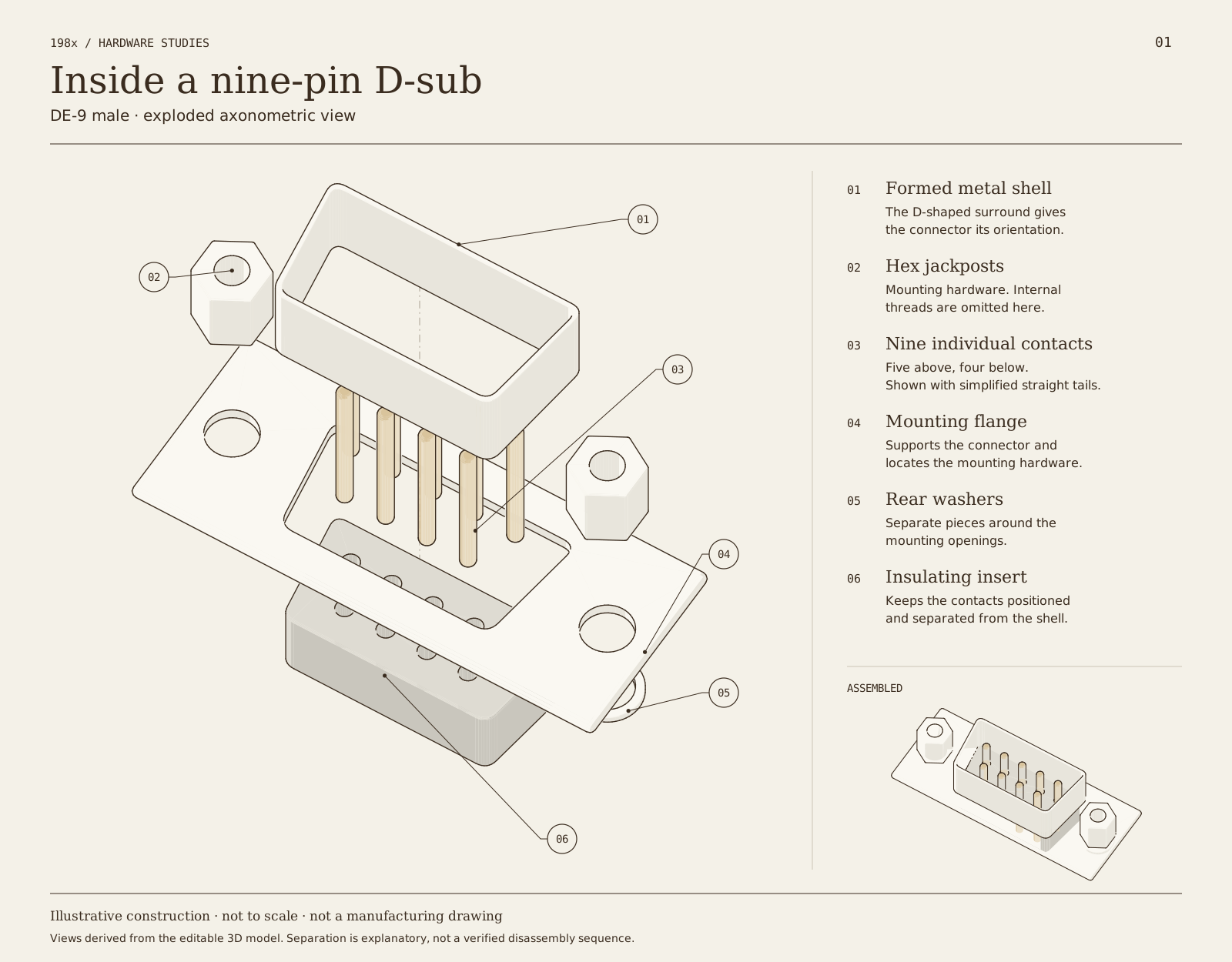
The exploded drawing below separates the pieces so we can follow their relationships. The contacts pass through holes in the insulating insert, which keeps them in position and apart. The metal shell surrounds the mating area; the flange and mounting hardware hold the assembly to a case or cable.
Each part needs different properties. Amphenol’s economy-range datasheet specifies a steel shell, a thermoplastic insulator and copper-alloy contacts with a thin gold finish over nickel: a strong surround, an insulator between the contacts, and contacts that conduct and resist corrosion. Atari’s version skipped some of this. Its console sockets were moulded plastic, without the metal shell or the pair of screws that normally lock a D-sub plug in place.
These drawings are simplified illustrations. Threads and contact-retention features are left out, and the contact tails are drawn as straight cylinders. The separation explains the parts; it is not a disassembly sequence or a set of manufacturing dimensions.
What does DE-9 mean?
In the standard-density range, the letter gives the shell size and the number the contacts. E is the shell used for nine contacts and B the larger shell used for 25, which gives DE-9 and DB-25. The letter is not another way of saying “connector”: a “DB-9” would be a nine-contact connector in a 25-contact shell. Amphenol’s shell-size overview separates shell sizes from contact counts, including the higher counts that fit into the same shells in high-density versions.
The male connector in the drawings has projecting pins. Its mating partner uses socket contacts, and Amphenol lists separate nine-way pin and socket versions.
Example: the C64 control ports
This is a C64 pinout, not a general assignment for nine-pin D-sub connectors, though it matches Atari’s. Look directly into the computer’s male port, with the wider row at the top. Looking into the mating cable socket reverses the picture, so do not transfer left-to-right positions between those views.
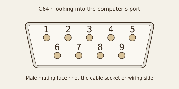
| Pin | C64 signal and purpose |
|---|---|
| 1 | Up: joystick direction. |
| 2 | Down: joystick direction. |
| 3 | Left: joystick direction. |
| 4 | Right: joystick direction. |
| 5 | POT Y: analogue paddle input. |
| 6 | Fire: button input; control port 1 also uses this contact for the light pen. |
| 7 | +5 V: power for suitable peripherals; the manual gives a maximum load of 50 mA. |
| 8 | Ground: the voltage reference and the joystick switches’ common connection. |
| 9 | POT X: analogue paddle input. |
The manual names the analogue inputs POT AY/AX on port 1 and POT BY/BX on port 2; the paddle controller entry explains how the SID reads them. The direction and fire inputs are active low: a digital joystick closes a switch to ground to signal a press.
The ports have the same pin assignments but reach different CIA register bits. Control port 1 uses CIA #1 port B at $DC01 (56321); control port 2 uses port A at $DC00 (56320). Fire is bit 4 in each case. The same lines take part in keyboard scanning, so their direction settings and the keyboard matter when a program reads them.
From the fire button to a bit
Follow control port 2, pin 6. With that CIA line set as an input, a pull-up holds the unpressed fire input high. Pressing fire closes the joystick switch between pin 6 and ground at pin 8. The input goes low, and bit 4 of $DC00 reads as zero. Releasing the button opens the switch and the input returns high.
That ground connection is intentional. It pulls down a signal that has only a weak pull-up behind it; it does not join the +5 V supply to ground.
Why the wrong device can damage a port
The shell checks orientation, not electrical compatibility. A wrong device might do nothing or give the wrong inputs. Damage becomes possible when its wiring or electronics make a connection the computer was not designed to tolerate, and there are several ways that can happen.
A short from power to ground. Suppose an incompatible device or miswired cable connects C64 pin 7 directly to pin 8. That joins +5 V to ground through a low-resistance path: a short circuit. Only the wiring, the power supply and any protection then limit the current, not the intended peripheral load. The result can be a voltage drop, a reset, heating or damage. The manual’s 50 mA rating is a limit for the peripheral, not a promise that the circuit holds every fault to 50 mA. This follows from the pinout; it is not a claim that every incompatible controller makes this connection.
Two outputs fighting. A peripheral with electronics inside may drive a line high while the computer drives it low. This is called output contention: current flows through both competing output stages, which can stress the chips. A passive joystick switch cannot do this. The CIA’s port lines can be outputs as well as inputs, and keyboard scanning uses them that way, which is one reason not to assume they only listen.
The wrong voltage. RS-232 serial signals swing below ground as well as above it. They are not the logic-level inputs the C64’s joystick circuit expects, and feeding one into a CIA pin can exceed the chip’s maximum ratings. An adapter that only rearranges wires does not translate voltage levels.
Before connecting a device, check what machine and interface it was made for, its pin assignments, its supply needs and its signal levels. Switch the equipment off before connecting or disconnecting these older control-port devices; powering off does not make incompatible wiring safe once the power returns.
When compatibility depends on a switch
A controller labelled multi-system may need the right setting before it is connected. If a selector changes which pin a button reaches, its position changes the electrical circuit as well as the button’s job.
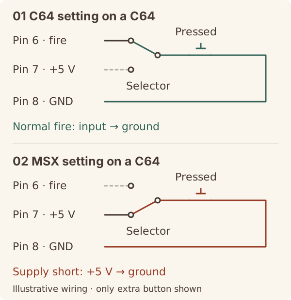
The MSX standard shows why. The MSX2 Technical Handbook draws a joystick whose switches all return to pin 8, which the computer drives low when it reads the stick, and its second trigger joins pin 7 to pin 8. On a C64, those same pins carry +5 V and ground. A joystick wired the MSX way can seem to work on a C64 until the second button is pressed: the directions and first fire button still close to pin 8, which is ground on the C64, but the second button shorts the supply.
The drawing below shows one way a selector could change that connection. In the C64 position, the extra button duplicates the normal fire button on pin 6. In the MSX position, it becomes a separate trigger on pin 7. Both use pin 8 as the switch common. This is an illustrative circuit, not the wiring of a particular commercial controller, and real switches may change other connections too.
A switch’s label matters too. A button-swap switch exchanges the buttons’ jobs; an autofire switch repeats the fire signal. Neither promises that the controller rewires itself for another machine. Check the instructions for the exact model and select the intended system before connecting it with the equipment switched off.
Sources
- Atari, Operating System User’s Manual (1982), section 11, pp. 175–176: the controller-port pin functions for the Atari 400/800 and the 50 mA supply limit.
- Atari, 2600/2600A VCS Domestic Field Service Manual (1983): the trigger signal at pin 6 of each controller connector.
- Joe Decuir, engineering notebook (Atari, 1977; unpublished): the VCS controller connector specified as a DE-9S, and the 400/800 ports as the same part.
- Commodore, Commodore 64 Programmer’s Reference Guide (1982): appendix I, p. 395 (control-port pinout and the 50 mA rating); pp. 328–329 (CIA register map); “The Game Ports”, pp. 343–344 (joystick switches, active-low fire); appendix M, pp. 422, 427 and 429 (6526 CIA maximum ratings, pull-ups and bidirectional ports). https://www.commodore.ca/manuals/c64_programmers_reference/c64-programmers_reference_guide-07-appendices.pdf
- CRASH issue 3, April 1984: AGF programmable joystick interface advertisement, “You can use any Atari-compatible joystick controller with any software for your Sinclair Spectrum”.
- Sinclair User issue 55, October 1986: Spectrum +2 review, the “standard Atari-style D-shaped plug” wired “differently from normal” and the SJS1 warning.
- CRASH issue 35, December 1986, p. 108: Frel Ltd advertisement for the £2.50 “PLUS TWO converter”.
- Commodore-Amiga, Amiga Hardware Reference Manual, second edition: appendix E (parallel, serial, game controller and external disk connectors; controller port devices on p. 305) and chapter 8 (the 23-pin video connector). https://amigadev.elowar.com/read/ADCD_2.1/Hardware_Manual_guide/node0000.html
- IBM, Personal Computer XT Technical Reference, revised edition, April 1983: printer adapter (p. 1-117), colour/graphics adapter (p. 1-133), game control adapter (p. 1-211), asynchronous communications adapter (p. 1-223).
- ASCII Corporation, MSX2 Technical Handbook, chapter 5, section 5.2 and figure 5.23: the joystick circuit and trigger B. https://konamiman.github.io/MSX2-Technical-Handbook/md/Chapter5a.html#52-joystick-use
- Duy Nguyen, Texas Instruments, RS232 Design Guide, SDAA219 (March 2026), sections 2 and 3.3: RS-232 cable-side voltages against logic levels. https://www.ti.com/lit/pdf/SDAA219
- Amphenol, D-Subminiature (D-sub) Economy Range Connectors, datasheet, pp. 2–5: materials, pin and socket versions. https://cdn.amphenol-cs.com/media/wysiwyg/files/documentation/datasheet/inputoutput/io_dsub_economy.pdf
- Amphenol, “D-Sub connectors” product overview: shell sizes and contact counts. https://www.amphenol-cs.com/connectors/d-sub.html
- Wikipedia, “D-subminiature” (web, secondary): Cannon’s introduction of the series in 1952; the Atari console sockets’ moulded plastic bodies without shield or screws. https://en.wikipedia.org/wiki/D-subminiature