
A chunky maze wall is a good fit for the TIA. So is a huge letter. Prepare their bits in RAM, then let a fixed kernel deliver them to the television. The preparation can be reusable code; the delivery still has to happen on time, every field.
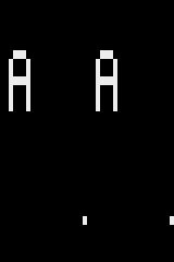
Include, initialise, call
Copy playfield.inc and kernel.inc, and include each once. Reserve 72 picture bytes at PF_BUFFER=$80 and 16 context bytes at PF=$C8. The complete caller leaves results at $D8–$E7, guards at $E8–$EB and 20 stack bytes at $EC–$FF. Those allocations fit the machine’s 128 bytes of RIOT RAM; they are not free space for another routine.
First call pf_clear. To set or erase a cell, put column 0..19 at PF+2, band 0..23 at +3 and 1=set or 0=erase at +4, then call pf_cell. PF+5 returns 1 when accepted, 0 when rejected. Invalid requests reject before any buffer write. Inputs survive; A/X/Y/flags and PF+5..7 are clobbered. Clear zeroes the buffer without setting a status.
This maintained caller stamps a letter, sets the boundary cell and tries an out-of-bounds request:
Prepare picture data outside the visible kernel
    jsr pf_clear
    lda #<glyph
    sta PF
    lda #>glyph
    sta PF+1
    lda #2
    sta PF+2
    lda #4
    sta PF+3
    jsr pf_stamp
    lda PF+5
    sta RESULT
    lda #19
    sta PF+2
    lda #23
    sta PF+3
    lda #1
    sta PF+4
    jsr pf_cell
    lda PF+5
    sta RESULT+1
    inc PF+2                  ; invalid x: must leave buffer alone
    jsr pf_cell
    lda PF+5
    sta RESULT+2
    lda #$a5
    sta $e8
    sta $eb
pf_stamp takes a pointer at PF+0/1 and an origin at +2/+3. Its seven source bytes use five low bits per row, bit 4 leftmost. Bits 7..5 must be zero. It checks the entire request before drawing, including all seven rows. A whole 5×7 stamp fits only at x<=15, y<=17. Zero bits erase existing cells: this is an opaque stamp. Source pointer and origin survive; +4..12 are scratch/status, with +5 returning 1/0.
Keep the source readable, stable, non-wrapping and disjoint from writable allocations. Use decimal mode clear. The shared context is not re-entrant. Reserve two stack bytes per direct call; stamping needs four because it calls the cell helper, plus your caller/interrupt depth. Neither helper changes interrupt state or video, sound or bank registers.
Give the kernel its own time
pf_kernel emits 24 bands of eight scanlines. It owns WSYNC and PF0/1/2 while running, clobbering A/Y/flags and PF+13/14. Your field caller owns VSYNC, VBLANK, colours, repetition/reflection and blanking work. Clear stale PF registers before unblanking, call the kernel at its scheduled boundary, then finish its final line with WSYNC before blanking. The complete caller below shows that sequence.
The fixed visible-line schedule
; Enter in horizontal blank at start of first picture line.
; NTSC: 24 bands, eight scanlines each. Caller clears VBLANK beforehand.
; No JSR, input, sound or buffer changes inside this loop.
; PF stores finish at CPU cycles 7,14,21 after each WSYNC release.
pf_kernel:
    ldy #0
    lda #24
    sta PF+14
pf_kernel_band:
    lda #8
    sta PF+13
pf_kernel_line:
    sta $02                   ; WSYNC: next scanline boundary
    lda PF_BUFFER,y           ; 4 cycles, no page crossing at $80..$c7
    sta $0d                   ; PF0, write ends at cycle 7
    lda PF_BUFFER+1,y
    sta $0e                   ; PF1, cycle 14
    lda PF_BUFFER+2,y
    sta $0f                   ; PF2, cycle 21 (visible starts at 22 2/3)
    dec PF+13
    bne pf_kernel_line
    iny
    iny
    iny
    dec PF+14
    bne pf_kernel_band
    rts                       ; caller must finish this final line before blanking
pf_kernel_end:
At this allocation, each indexed buffer read takes four CPU cycles. After WSYNC releases, the three register writes finish at cycles 7, 14 and 21. Visible output begins at colour clock 68: CPU cycle 22⅔. Moving the buffer so an indexed read crosses a page changes that schedule. Adding work inside the loop changes it too. Input, music and picture preparation belong outside this kernel.
The caller measures 59,736 colour clocks per field: 262×228. The picture contains 192 emitted lines. This emulator’s 240-row capture includes the surrounding viewport; the first emitted line appears at y14 here. That capture offset is not a game-coordinate rule. PAL needs its own caller and verification.
Use the grid you actually have
Each independent cell spans four colour clocks horizontally and eight scanlines vertically. There are 20 independent columns. CTRLPF bit 0 chooses whether the right half repeats or reflects them. Forty positions on the television do not give this kernel forty independent columns.
PF0 scans bits 4,5,6,7; PF1 scans 7..0; PF2 scans 0..7. The helper handles this awkward packing. A logical point (13,19) maps to cell (3,2), with remainders (1,3). A 5×7 glyph therefore occupies 20×56 colour clocks/scanlines before repetition or reflection. Its drawing grid need not be your game’s collision grid.
Place a point develops grid conversion and remainders. Move a glyph connects stored rows with positions. Here the maths also explains a useful constraint: reflection can give a maze symmetry without storing another half.
Pay for the picture
The components assemble to 197 code bytes plus 64 table bytes, with 72 picture bytes and 16 context bytes. Each glyph adds seven source bytes. Clear makes 72 writes; a cell makes one; a stamp makes 35 cell calls/writes after seven validation reads. These are work counts, not measured helper durations. Many stamps may exceed your blanking budget.
The kernel’s visible CPU cost recurs even when nothing changes. A ROM-only picture or fewer bands can save RAM. Independent right-side detail needs an asymmetric kernel with carefully timed mid-line writes. Players, missiles, the ball, changing colours and finer lettering need their own register and cycle contracts. This component supplies no general pixel, line, circle or arbitrary-size font API.
Read the reusable helpers and complete NTSC caller
Reusable picture preparation
; Caller supplies PF_BUFFER (72 bytes) and PF (16 zero-page bytes).
; PF+2=x, +3=y, +4=0/1; +5=accepted. A/X/Y/flags clobbered.
pf_clear:
    lda #0
    ldx #71
pf_clear_loop:
    sta PF_BUFFER,x
    dex
    bpl pf_clear_loop
    rts
pf_cell:
    lda #0
    sta PF+5
    ldx PF+2
    cpx #20
    bcs pf_cell_return
    ldy PF+3
    cpy #24
    bcs pf_cell_return
    lda PF+4
    cmp #2
    bcs pf_cell_return
    lda pf_rows,y
    clc
    adc pf_bytes,x
    tay
    lda pf_masks,x
    sta PF+6
    lda PF+4
    beq pf_cell_erase
    lda PF_BUFFER,y
    ora PF+6
    bne pf_cell_store
pf_cell_erase:
    lda PF+6
    eor #$ff
    and PF_BUFFER,y
pf_cell_store:
    sta PF_BUFFER,y
    inc PF+5
pf_cell_return:
    rts
; Opaque 5x7 stamp: PF+0/1 -> seven bytes, low five bits, bit4 left.
; Reject complete request before writing. Restores origin; clobbers PF+4.
pf_stamp:
    lda #0
    sta PF+5
    lda PF+2
    cmp #16
    bcs pf_stamp_return
    lda PF+3
    cmp #18
    bcs pf_stamp_return
    ldy #6
pf_stamp_validate:
    lda (PF),y
    cmp #32
    bcs pf_stamp_return
    dey
    bpl pf_stamp_validate
    lda PF+2
    sta PF+8
    lda PF+3
    sta PF+9
    lda #0
    sta PF+10
pf_stamp_row:
    ldy PF+10
    lda (PF),y
    sta PF+12
    lda #5
    sta PF+11
pf_stamp_column:
    lda PF+12
    and #16
    beq pf_stamp_zero
    lda #1
pf_stamp_zero:
    sta PF+4
    jsr pf_cell
    asl PF+12
    inc PF+2
    dec PF+11
    bne pf_stamp_column
    lda PF+8
    sta PF+2
    inc PF+3
    inc PF+10
    lda PF+10
    cmp #7
    bne pf_stamp_row
    lda PF+9
    sta PF+3
pf_stamp_return:
    rts
pf_rows:
    !for row,0,23 { !byte row*3 }
pf_bytes:
    !byte 0,0,0,0,1,1,1,1,1,1,1,1,2,2,2,2,2,2,2,2
pf_masks:
    !byte $10,$20,$40,$80,$80,$40,$20,$10,$08,$04,$02,$01
    !byte $01,$02,$04,$08,$10,$20,$40,$80
pf_data_end:
Complete allocation, reset and field caller
PF_BUFFER = $80
PF = $c8
RESULT = $d8
* = $f000
start:
    sei
    cld
    ldx #$ff
    txs
    lda #2
    sta $01
    lda #0
    sta $00
    sta $09
    sta $0a                   ; repeat right half; use 1 for reflection
    lda #14
    sta $08
    jsr pf_clear
    lda #<glyph
    sta PF
    lda #>glyph
    sta PF+1
    lda #2
    sta PF+2
    lda #4
    sta PF+3
    jsr pf_stamp
    lda PF+5
    sta RESULT
    lda #19
    sta PF+2
    lda #23
    sta PF+3
    lda #1
    sta PF+4
    jsr pf_cell
    lda PF+5
    sta RESULT+1
    inc PF+2                  ; invalid x: must leave buffer alone
    jsr pf_cell
    lda PF+5
    sta RESULT+2
    lda #$a5
    sta $e8
    sta $eb
ready:
frame:
    lda #2
    sta $01
    sta $02
    sta $00
    sta $02
    sta $02
    sta $02
    lda #0
    sta $00
    ldx #36                   ; kernel begins with its own WSYNC
blank:
    sta $02
    dex
    bne blank
    lda #0
    sta $0d
    sta $0e
    sta $0f
    sta $01
    jsr pf_kernel
    sta $02                   ; finish final picture line, then blank
    lda #2
    sta $01
    ldx #29                   ; one extra WSYNC at frame start = 30 overscan
overscan:
    sta $02
    dex
    bne overscan
    jmp frame
!source "playfield.inc"
!source "kernel.inc"
glyph:
    !byte 14,17,17,31,17,17,17
    !fill $fffc-*, $ff
    !word start,start
Make it your own
Turn the letter demonstration into a tiny maze. The separate customise/ caller builds walls and passages, stamps an original arrow and chooses a new foreground colour. It uses the same two includes, buffer and kernel. The original working example stays available above.
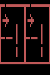
Replace the picture, keep its format
Keep customise/ beside playfield.inc and kernel.inc, and run make there. Load build/maze.a26 for repetition or build/reflected.a26 for reflection. Both small wrappers include the same caller.inc. To bring this into your game, copy the parent includes and reserve the documented buffer/context first; then adapt the preparation calls, not the kernel’s visible-line schedule.
Replace these seven source values with your own five-bit rows. Here 4 is binary 00100, 2 is 00010, and 31 fills all five dots. Bit 4 is the left edge. Each row must remain 0..31, and the whole stamp must fit its origin. The arrow is placed at (2,4); changing PF+2/PF+3 moves it within the existing bounds. Its zero bits erase what was underneath.
Replace seven rows to make your own glyph
; BEGIN CUSTOM GLYPH
    !byte 4,2,31,2,4,0,0      ; original right-pointing arrow
Walls use ordinary pf_cell calls with value 1. A doorway is a call with value 0. The complete caller draws the perimeter, two interior walls with passages, then the arrow; edit those coordinates to make another room. Drawing order matters because the stamp is opaque. These are pictures and passages, not collision or pathfinding rules: your game can keep a separate logical map.
Change colour or reflect the room
The foreground changes from $0E to $46 before the first field; COLUBK remains zero. The selected NTSC emulator shows this as a rose-red playfield. Choose another register value in setup, then check contrast in your target model. Physical colour and other video standards are not established by this capture.
Choose the foreground before visible emission
; BEGIN CUSTOM COLOUR
    lda #$46                  ; chosen NTSC foreground; background stays black
    sta $08
Set MAZE_REFLECT to 0 for repetition or 1 for reflection. This complete reflected wrapper changes that choice without adding a second stored half:
Reflect the same prepared half-picture
MAZE_REFLECT = 1
!source "caller.inc"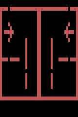
Know what the variation costs
| Resource or work | Original caller | Maze caller |
|---|---|---|
| Reusable code + tables | 197 + 64 bytes | Same |
| Picture + context | 72 + 16 bytes | Same |
| Glyph source | 7 bytes | 7 replacement bytes |
| Setup writes to picture, including clear | 108 | 213 |
| Startup instruction span, start to ready | 81 bytes | 162 bytes |
| Measured colour clocks per steady field | 59,736 | 59,736 |
The maze makes 84 perimeter cell writes, 21 interior-wall writes, one doorway erase and 35 opaque stamp writes: 141 after the 72-write clear. That preparation happens once before the first field. A game updating the picture every field must measure its own blanking workload. The startup span is assembled code size, not CPU execution time; both cartridges remain 4 KiB.
New row data, valid cell coordinates and setup colour/reflection choices preserve this contract. Changing the band height does not. Keeping 192 picture lines with four-line bands would require 48 bands: at three bytes each, 144 picture bytes, already more than all 128 bytes of RIOT RAM before context or stack. A different buffer strategy and kernel would be needed. Extra visible-loop work, asymmetric halves, relocated indexed buffers and shared video ownership also need renewed timing verification.
Read the complete maze preparation and field caller
Custom picture using the unchanged reusable includes
PF_BUFFER = $80
PF = $c8
RESULT = $d8
* = $f000
start:
    sei
    cld
    ldx #$ff
    txs
    lda #2
    sta $01
    lda #0
    sta $00
    sta $09
    lda #MAZE_REFLECT
    sta $0a                   ; caller configuration: 0 repeat, 1 reflect
; BEGIN CUSTOM COLOUR
    lda #$46                  ; chosen NTSC foreground; background stays black
    sta $08
; END CUSTOM COLOUR
; BEGIN CUSTOM PICTURE
    jsr pf_clear
    lda #1
    sta PF+4
    lda #19
    sta PF+2
horizontal_walls:
    lda #0
    sta PF+3
    jsr pf_cell
    lda #23
    sta PF+3
    jsr pf_cell
    dec PF+2
    bpl horizontal_walls
    lda #22
    sta PF+3
vertical_walls:
    lda #0
    sta PF+2
    jsr pf_cell
    lda #19
    sta PF+2
    jsr pf_cell
    dec PF+3
    bne vertical_walls
    lda #9
    sta PF+2
    lda #13
    sta PF+3
inner_horizontal:
    lda PF+2
    cmp #4                    ; leave a passage
    beq next_horizontal
    jsr pf_cell
next_horizontal:
    dec PF+2
    bpl inner_horizontal
    lda #13
    sta PF+2
    lda #20
    sta PF+3
inner_vertical:
    lda PF+3
    cmp #16                   ; another passage
    beq next_vertical
    jsr pf_cell
next_vertical:
    dec PF+3
    lda PF+3
    cmp #7
    bne inner_vertical
    lda #4                    ; doorway: erase one top-wall cell
    sta PF+2
    lda #0
    sta PF+3
    sta PF+4
    jsr pf_cell
    lda #<glyph
    sta PF
    lda #>glyph
    sta PF+1
    lda #2
    sta PF+2
    lda #4
    sta PF+3
    jsr pf_stamp
    lda PF+5
    sta RESULT
    lda #$a5
    sta $e8
    sta $eb
; END CUSTOM PICTURE
ready:
frame:
    lda #2
    sta $01
    sta $02
    sta $00
    sta $02
    sta $02
    sta $02
    lda #0
    sta $00
    ldx #36                   ; kernel begins with its own WSYNC
blank:
    sta $02
    dex
    bne blank
    lda #0
    sta $0d
    sta $0e
    sta $0f
    sta $01
    jsr pf_kernel
    sta $02                   ; finish final picture line, then blank
    lda #2
    sta $01
    ldx #29                   ; one extra WSYNC at frame start = 30 overscan
overscan:
    sta $02
    dex
    bne overscan
    jmp frame
!source "../playfield.inc"
!source "../kernel.inc"
glyph:
; BEGIN CUSTOM GLYPH
    !byte 4,2,31,2,4,0,0      ; original right-pointing arrow
; END CUSTOM GLYPH
    !fill $fffc-*, $ff
    !word start,start
Both customisation builds were assembled and executed in the same released native emulator. The entire buffer and every frame pixel match an independent logical maze/arrow model; guards and steady field periods pass. The colour expectation belongs to that emulator’s NTSC palette. See the linked source directory’s customise/README.md and captures to reproduce the checks.
Common mistakes and their symptoms
These examples are deliberately broken. Keep the working includes above as your starting point. Each wrong fragment was assembled into this caller, run in the same NTSC emulator and checked against an independently predicted result. The corrected fragments were run too.
Part of the letter is scrambled
Symptom: the leftmost part of each A is mangled, but the rest of the letter stays in place. This is a packing error, not a reason to move the whole glyph.
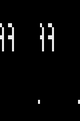
Cause: the first four cells use PF0’s high nibble. Treating that nibble as most-significant-bit first reverses those four columns. PF1 really does scan most-significant-bit first; applying its rule to PF0 is the mistake.
Deliberately wrong: PF0 masks run backwards
; BEGIN WRONG
    !byte $80,$40,$20,$10,$80,$40,$20,$10,$08,$04,$02,$01
Fix: restore PF0’s order to bits 4,5,6,7, leaving the other masks alone. Compare the whole buffer and picture with the known-good result; a glyph that happens to be symmetric can hide this error.
Correct: each register keeps its own bit order
; BEGIN FIX
    !byte $10,$20,$40,$80,$80,$40,$20,$10,$08,$04,$02,$01
Small notches appear at a band boundary
Symptom: a few pixels at the left of the first A are wrong where its shape changes between eight-line bands. The repeated A on the right is intact. That difference is a timing clue.
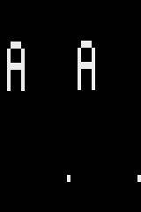
Cause: $EA is the two-cycle NOP instruction. These twelve bytes do nothing useful, but cost 24 cycles. PF0 and PF1 are now written at cycles 31 and 38 instead of 7 and 14, too late for their left-side output. At a band transition, those regions use the previous band’s bits. By the time the beam reaches the repeated right half, the new bits are ready. Most lines within a band look fine because their data did not change.
Deliberately wrong: add 24 cycles before the first buffer read
; BEGIN WRONG
    !fill 12,$ea
    lda PF_BUFFER,y
Fix: remove the delay and put extra work outside the visible kernel. Restore the scheduled read below and retain the following PF0 store. Check transitions in an asymmetric picture, as well as the cycle schedule; a constant fill can conceal a late write.
Correct: keep the first read on its scheduled cycle
; BEGIN FIX
    lda PF_BUFFER,y
The picture looks right, but the field is too long
Symptom: this emulator still produces the familiar letter, yet one field takes an extra scanline. A screenshot alone cannot diagnose it.
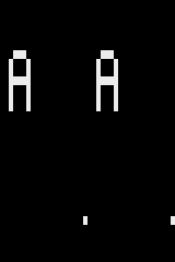
Cause: the selected caller already accounts for one overscan WSYNC at the frame start. Increasing its other overscan loop from 29 to 30 adds another line. Count all the caller’s waits, including the kernel boundary and the final picture line, rather than choosing a loop count in isolation.
Deliberately wrong: add one overscan line
; BEGIN WRONG
ldx #30| This caller | Lines per field | Measured colour clocks between steady field markers |
|---|---|---|
| Working | 262 | 59,736 |
| Extra overscan wait | 263 | 59,964 |
Fix: restore 29 in this caller, then measure between the same steady CPU markers again. The difference is 228 colour clocks: exactly one scanline. That count belongs to this NTSC caller, not every TIA kernel or PAL configuration.
Correct for this caller's complete field schedule
; BEGIN FIX
    ldx #29
What was verified
Asm198x 0.0.71 and released Emu198x 0.41.0 execute this original 4 KiB reset cartridge without firmware. Every native frame pixel and all 72 picture bytes are compared with a separate logical-grid model, in repetition and reflection builds. Native call markers and the measured field period guard against incomplete execution. Six rejected boundary calls leave the whole buffer unchanged. Completed wrong-bit, late-register and extra-scanline controls fail the same checks. The website’s pinned Asm198x 0.0.65 also assembles it.
All three corrected diagnostic fragments also reproduce the working frame. The native verifier checks each broken capture against its predicted symptom, then requires the repaired path to pass the original destination and timing checks.
This is evidence for this caller and emulator configuration, not original hardware, PAL, arbitrary relocation or coexistence with another kernel.
- Reusable source, caller and execution records
- Contracts, costs and reproduction
- Steve Wright, Atari, Stella Programmer’s Guide, playfield discussion and printed p39 serial-output diagram.
- Build objects for the very different MARIA display.