
Draw a number above an enemy and let it rise. The digits keep their shape while their position changes. That little effect gives us translation, clipping and byte boundaries in one useful example.
The Pattern Library’s bitmap text routines already do the drawing on Spectrum, BBC Micro, Dragon, CPC and Amiga. Here we’ll work through the maths you use to place a label and understand what it costs.
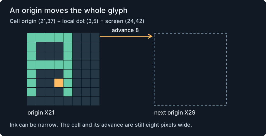
Add an origin
A font describes dots relative to the character’s own top-left corner. Our highlighted dot is three pixels right and five down: local (3,5). Put the cell at (21,37), and add:
screenX = 21+3 = 24
screenY = 37+5 = 42
Move the origin to (25,35), and that dot lands at (28,40). Every dot moves four right and two up. Distances between dots stay the same because each received the same displacement. That is translation.
These are screen coordinates, with Y increasing downwards. Place a point uses an upwards world Y; convert deliberately when moving between them. The glyph’s origin is its cell corner, not a typographic baseline.
The picture is not its advance
The supplied design has five columns of ink inside an eight-pixel cell. The next glyph begins eight pixels after the previous origin: 21, 29, 37, 45. A space has no ink, but it still takes one cell.
For n characters, nextX = startX + 8*n. A ten-code label starting at 21 ends at 101. That is the position after the label, not necessarily the rightmost lit dot. To centre its cell bounds around X160, choose startX = 160 - (10*8)/2 = 120.
A proportional font would have a different advance for each character, so we would add those advances instead. Scaling, word wrapping and baseline alignment need their own rules. The current reusable component is deliberately fixed-width.
A three-character string begins at X21. Its middle character is a blank space. Where does the third cell begin, and what is nextX?
Show the explanation
The cell origins are 21, 29 and 37. The third begins at 37, and nextX is 45. Invisible ink does not remove the middle cell’s advance.
Find the byte and protect its neighbours
On an eight-pixel-per-byte bitmap, X21 gives 21 div 8 = 2 and 21 mod 8 = 5. Division selects byte-column 2; remainder says the cell begins five pixels into it. Its eight columns cross into byte-column 3.
The highlighted dot at X24 instead has quotient 3 and remainder 0, so its mask is bit 7: 128 >> 0 = 128. On a CPC MODE 1 display, divide by four: X21 selects byte-column 5, phase 1. An eight-pixel cell can touch three CPC bytes. Each pixel has two separated pen bits, so the actual mask comes from that backend rather than an eight-bit mono formula.
The machine page calculates the row address. BBC interleaving, Spectrum scanline ordering and CPC packing are different problems from translation. Keep those decisions in the backend, which pixels and spans already expose.
Clip the drawing, keep the layout
A scissor [0,32) across and [0,24) down allows X0..31 and Y0..23. Put a cell at X−3: only its local columns 3..7 can appear. A second cell still starts at X5. Clipping discards outside ink; it does not squeeze the layout sideways.
For a foreground run [−1,4), the intersection is [max(−1,0), min(4,32)) = [0,4). Draw only if the new start is less than the new end. A completely clipped glyph still advances by eight. The text routine accepts negative origins within its documented range and clips each row/run before calling its strict span backend.
Count useful work
An eight-row opaque glyph first paints eight background spans, then its foreground runs. Transparent mode draws only the foreground. The sample ten-code PIXEL TEXT has 77 foreground spans; opaque adds 80 backgrounds. Partial edge bytes may be visited by several runs.
On the mono backends, moving that label from X24 to X31 changes opaque byte writes from 157 to 237. Transparent writes remain 77 in this workload. CPC’s counts are 250 to 324 opaque and 90 to 84 transparent. Blank columns and ink runs matter: alignment alone cannot predict every count.
A masked blitter could combine background and foreground in fewer passes. Pre-shifted phases spend font storage to save draw-time work. A ten-digit font needs 80 bytes; 64 glyphs need 512; 256 need 2,048. Those choices let a game fit its own limits instead of assuming one renderer is best everywhere.
These are observed writes and storage sizes, not elapsed time. Measure the routine inside your actual frame before promising a frame rate. Use the machine-specific text entries for the real calls, ownership rules and separately verified results.
The Amiga implementation uses the same glyph and advance maths with wider source pointers. Its field offsets differ; the logical idea can travel without pretending every machine has the same representation.
Put a shared picture in a cell
A character display gives us another useful split. The picture lives in a slot; the screen cell holds its number. In the writable-character routines, replacing slot 1 changes every cell containing code 1. Selecting code 2 in one cell changes only that instance. A door and a wall may need different choices, even when their pictures are the same size.
On the seven qualified TMS Graphics I targets, slot n stores eight rows at n*8+r. Slot 8, row 5 is byte 69, or $0045. The last slot starts at 255*8 = 2040, or $07F8, and ends at $07FF. A cell at (31,23) has index 23*32+31 = 767; its bottom-right dot is at (31*8+7, 23*8+7) = (255,191).
Colour has another grouping: slots 0–7 share one colour byte, slots 8–15 share the next. Use slot div 8 to choose the group. Changing the bits of slot 8 does not change that colour byte; changing its colour can affect other pictures in slots 9–15. SVI-328’s entry shows the actual calls and its separate video read/write ports.
Slots 15 and 16 are next to each other. Do they share a Graphics I colour byte?
Show the explanation
No. 15 div 8 = 1, while 16 div 8 = 2. They cross a colour-group boundary even though the glyph row format stays the same.
When one slot needs more than a byte
Master System and Game Gear can select pattern 256. Its low byte is zero, but its high index bit is one: dropping that bit selects the wrong picture. In the checked allocation, pattern 447 begins at 447*32 = 14304, or $37E0. Four plane bytes per row combine pixel bits with weights 1, 2, 4 and 8.
NES CHR-RAM also uses planes, but stores eight low rows followed by eight high rows. The same logical two-bit value needs a different byte layout. C64 character RAM needs just one bit per pixel; its separate cell colour is another resource. These are useful cases of the same arithmetic producing different storage contracts.
The Game Gear window introduces a second origin: visible (0,0) is logical background (48,24). A logical point (64,40) therefore appears at (16,16). A correct map coordinate can lie outside the visible window; storage validity and visibility are different questions.
The code is not always the slot
Jupiter Ace and Atari mode 2 store 128 shapes. Screen code 255 selects slot 255 & 127 = 127 and an inverse flag; it does not require 256 stored pictures.
Oric TEXT gives us a different boundary. Its first 32 codes are controls, so this picture API starts at ASCII 32. A six-dot row 100001 is 33. In the selected allocation, logical (2,2) has index 2*37+2 = 76, but its physical name is at $BB80+2*40+3+2 = $BBD5. Thirty-seven is the drawable width; forty is the physical stride. The three reserved cells carry paper, ink and mode attributes, and the routine must step around them.
A code can choose a picture in ROM
PET and Aquarius place names in a fixed grid, but their stock font is in ROM. Selecting a different name changes the cell’s picture; it does not upload new dots. Aquarius adds a separate foreground/background byte, while the selected PET has no per-cell colour plane.
A block character can offer a coarser grid inside a cell. If the installed repertoire supplies all 2×2 block masks, coarse point (5,7) belongs to cell (5 div 2, 7 div 2) = (2,3), quadrant (5 mod 2, 7 mod 2) = (1,1). A lookup must translate that mask into the actual ROM code. The division works on every machine; the repertoire may not provide the picture you need.
ZX80 and ZX81 add another condition: the requested cell must already exist in a newline-terminated display row. The ZX80 caller’s ten-cell row cannot accept a 32-cell span. Screen dimensions describe possible positions; the current display file describes allocated storage. Keep those two bounds separate when turning a coordinate into a write.
A picture need not be a rectangular buffer
The TIA stamp expands seven five-bit rows into coarse playfield cells. PF0, PF1 and PF2 scan their bits in different directions, so the packing table handles something a simple row stride cannot. A fixed kernel still emits those cells every field.
The MARIA caller stores visible rows 256 bytes apart. Its zone OFFSET descends from 15 to zero, making the first row’s address base+15*256. Four 2-bit pixels still fit in each byte, with shift 6−2*(x mod 4). Pixel packing, row stride and screen placement are three separate calculations.
Fit rows without counting a final gap
Five rows of 8-pixel glyphs at a pitch of 16 need (5-1)*16+8=72 scanlines. Pitch measures origin-to-origin distance; the final row needs its own height, not another full gap. A panel can therefore hold the rows without reserving 80 scanlines for them.
Text layout keeps those quantities separate, checks the complete paragraph before drawing, and shows why character wrapping and word wrapping are different policies.
The word-aware bitmap-text variant uses integer cell capacity to choose a line break, then translates each aligned line into screen coordinates. Its examples show where preserving a word changes the number of rows.
The proportional text variants sum a width and spacing for each glyph. Six narrow letters can take less room than six wide ones. Use that same sum for centring, wrapping and the next drawing position; a fixed step in just one of those paths makes the visible result disagree with the calculation.
The integer-enlarged glyph routines turn one font pixel into a rectangle. Multiply source coordinates by the scale to place it; divide a destination-local coordinate by that scale to find its source pixel. Add the cell origin before clipping, so a cut-off letter keeps the same sampling phase.
The bitmap glyph transforms add another local operation before this translation: a quarter-turn maps (x,y) inside an 8×8 cell to (7−y,x). The machine entries include working routines, reflected variants and a wrong/fixed coordinate example. Rotating the ink does not rotate the arrangement of a whole string.
A larger glyph is still a grid
The four-tile character examples turn an 8×8 sketch into a 16×16 picture prepared as four ordinary tiles. Tile (tx,ty) selects first + ty*2+tx; its name-table position is origin + ty*32+tx. The two grids have different row strides: two tiles across the picture, 32 cells across the screen. Confusing them is enough to break the picture even when every write reaches valid video memory.